Arduino Examples
Arduino Examples
Note In addition to all Components listed in examples below, you will need connecting wires, a Breadboard and an Arduino (Uno).
Digital Output
- Blink Examples
Components: Atleast 2 LEDs and 2 resistors (220 Ohms)
Single LED
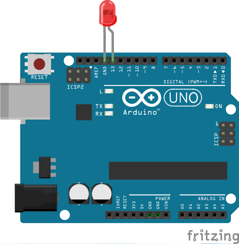
Code
  int led = 13;                   // integer variable led is declare
  void setup() {                  // the setup() method is executed only once
    pinMode(led, OUTPUT);         // the led PIN is declared as digital output
  }

  void loop() {                   // the loop() method is repeated
    digitalWrite(led, HIGH);      // switching on the led
    delay(1000);                  // stopping the program for 1000 milliseconds
    digitalWrite(led, LOW);       // switching off the led
    delay(1000);                  // stopping the program for 1000 milliseconds
  }
Multiple LEDs in Series
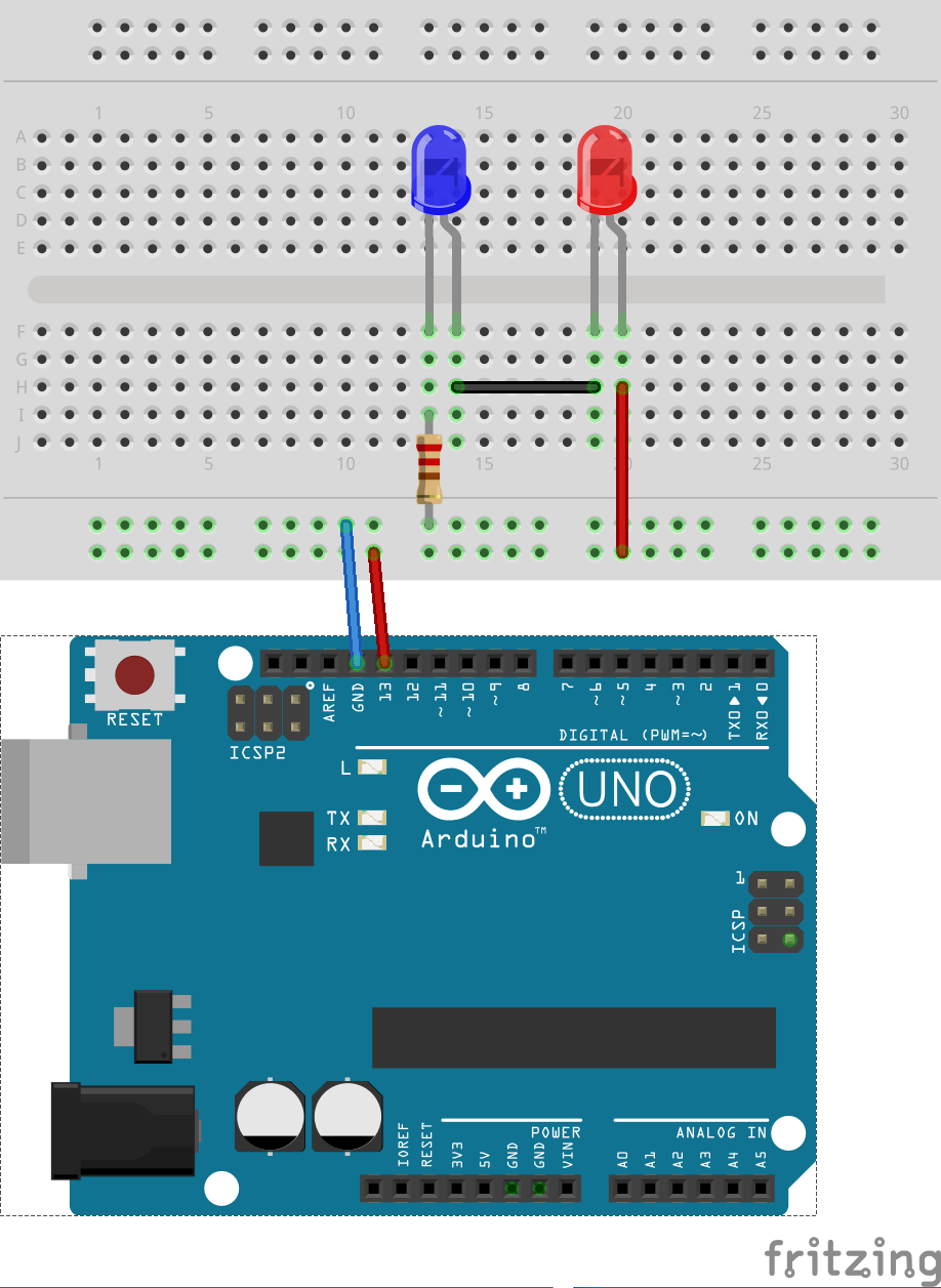
Code Use the same code as the single LED example.
Multiple LEDs in Parallel
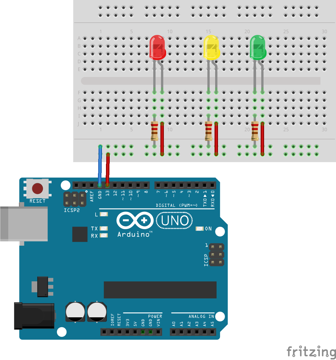
Code Use the same code as the single LED example.
Simple Traffic Light Simulation
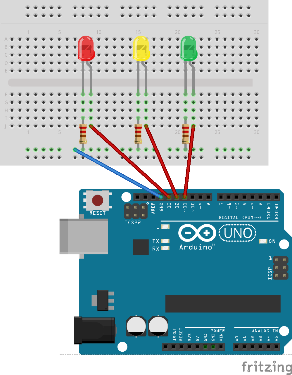
Code
  int led1 = 11;                   // integer variable led is declared
  int led2 = 12;
  int led3 = 13;

  void setup() {                  // the setup() method is executed only once
    pinMode(led1, OUTPUT);         // the led PIN is declared as digital output
    pinMode(led2, OUTPUT);
	  pinMode(led3, OUTPUT);
  }

  void loop() {                   // the loop() method is repeated
    digitalWrite(led1, HIGH);      // switching on the led
    digitalWrite(led2, LOW);      // switching on the led
    digitalWrite(led3, LOW);      // switching on the led
    delay(4000);                  // stopping the program for 1000 milliseconds
    digitalWrite(led1, LOW);      // switching on the led
    digitalWrite(led2, HIGH);      // switching on the led
    digitalWrite(led3, LOW);      // switching on the led
    delay(2000);                  // stopping the program for 1000 milliseconds
    digitalWrite(led1, LOW);      // switching on the led
    digitalWrite(led2, LOW);      // switching on the led
    digitalWrite(led3, HIGH);      // switching on the led
    delay(5000);                  // stopping the program for 1000 milliseconds
  }
Digital Input
-
Button Example
Components: 1x LED, 1x Resistor (10k Ohms), 1x Button
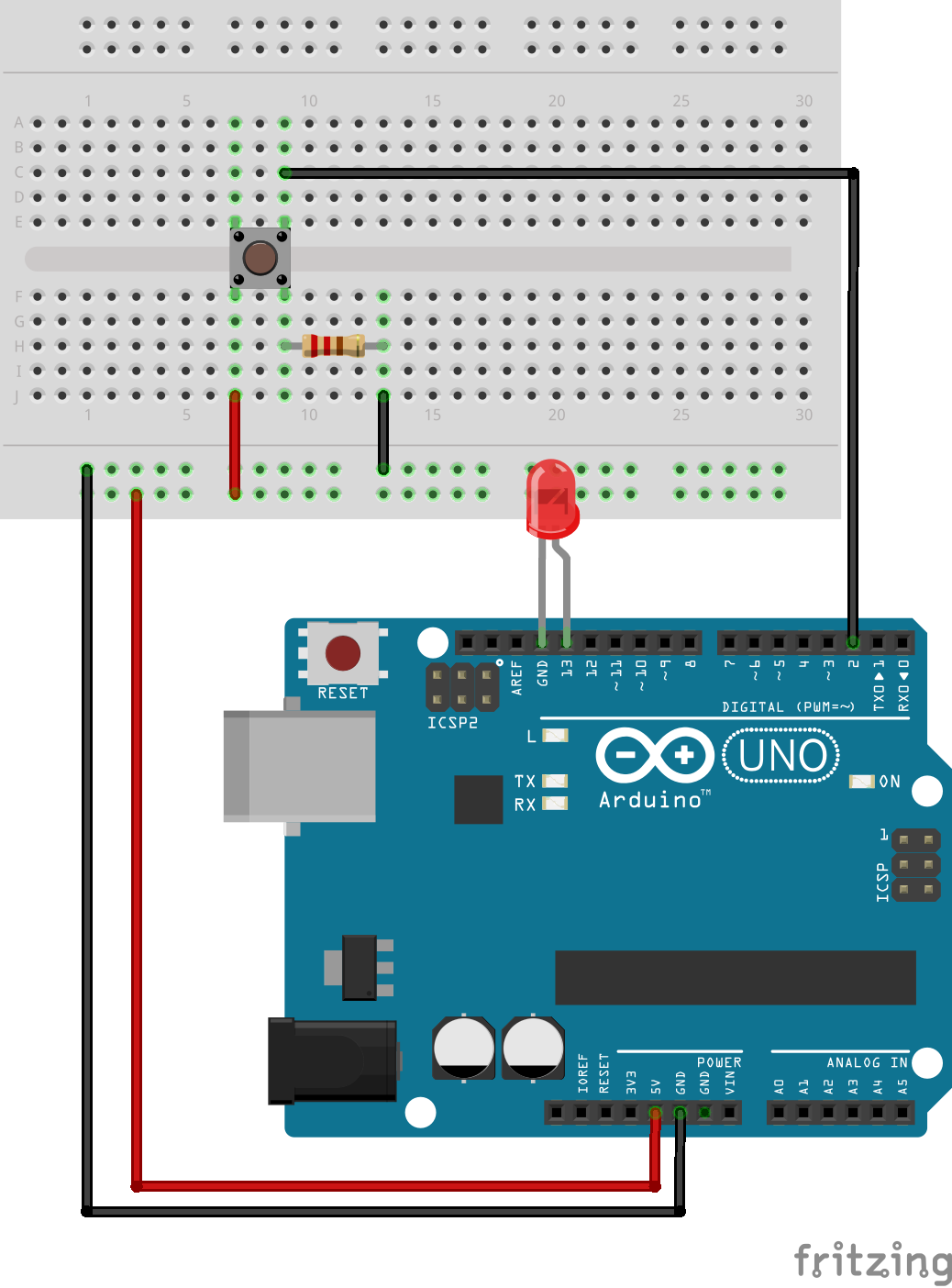
Code
const int buttonPin = 2; // the number of the pushbutton pin const int ledPin = 13; // the number of the LED pin // variables will change: int buttonState = 0; // variable for reading the pushbutton status void setup() { // initialize the LED pin as an output: pinMode(ledPin, OUTPUT); // initialize the pushbutton pin as an input: pinMode(buttonPin, INPUT); } void loop(){ // read the state of the pushbutton value: buttonState = digitalRead(buttonPin); // check if the pushbutton is pressed. // if it is, the buttonState is HIGH: if (buttonState == HIGH) { // turn LED on: digitalWrite(ledPin, HIGH); } else { // turn LED off: digitalWrite(ledPin, LOW); } } -
Tilt Switch Example
Components: 1x LED, 1x Resistor (100k Ohms), 1x Tilt Switch
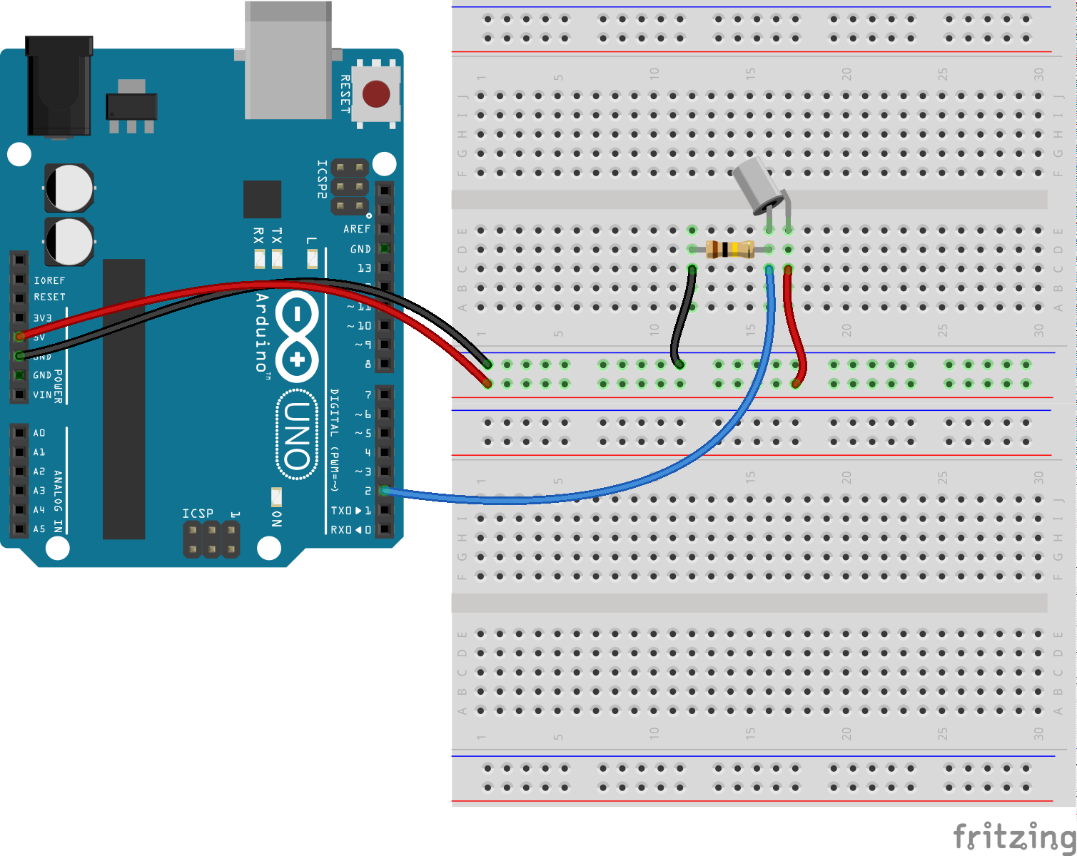
Code: Same as Button Example
Analog Input
-
Photocell / Photoresistor Example
Components: 1x LED, 1x Resistor (10k Ohms), 1x Photoresistor
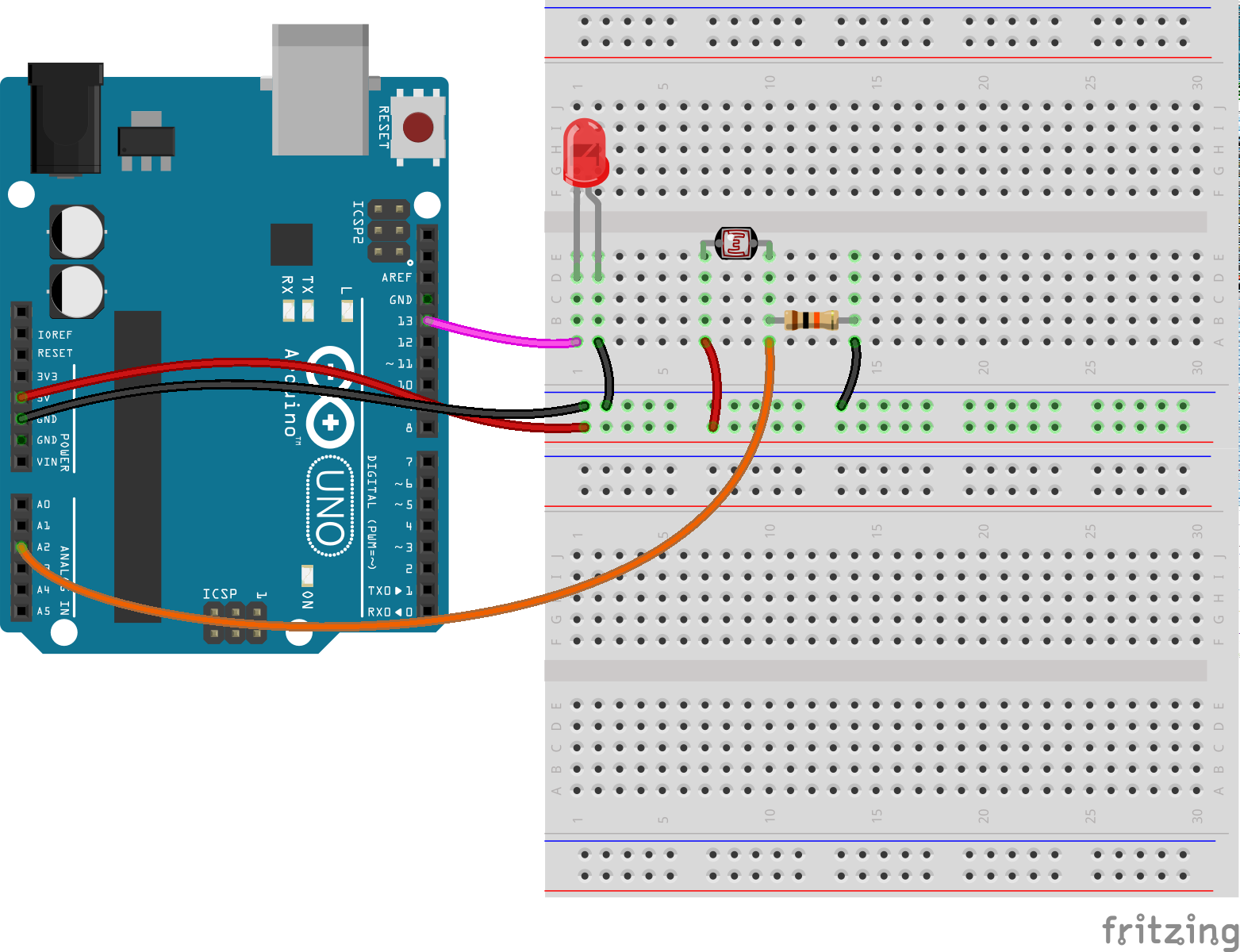
Code
int sensorPin = A2 ; // select the input pin for the potentiometer int ledPin = 13; // select the pin for the LED int sensorValue = 0; // variable to store the value coming from the sensor void setup() { // declare the ledPin as an OUTPUT: pinMode(ledPin, OUTPUT); } void loop() { // read the value from the sensor: sensorValue = analogRead(sensorPin); // turn the ledPin on digitalWrite(ledPin, HIGH); // stop the program for <sensorValue> milliseconds: delay(sensorValue); // turn the ledPin off: digitalWrite(ledPin, LOW); // stop the program for for <sensorValue> milliseconds: delay(sensorValue); } -
Potentiometer Example
Components: 1x LED, 1x Potentiometer
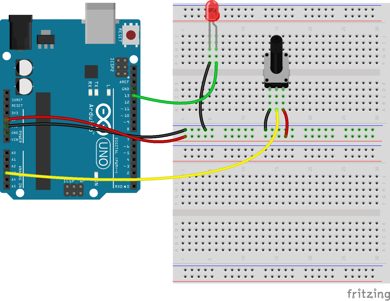
Code: Same as Photocell Example
Analog Output
-
RGB LED Example
Components: 1x RGB LED, 3x Resistors (220 Ohms)
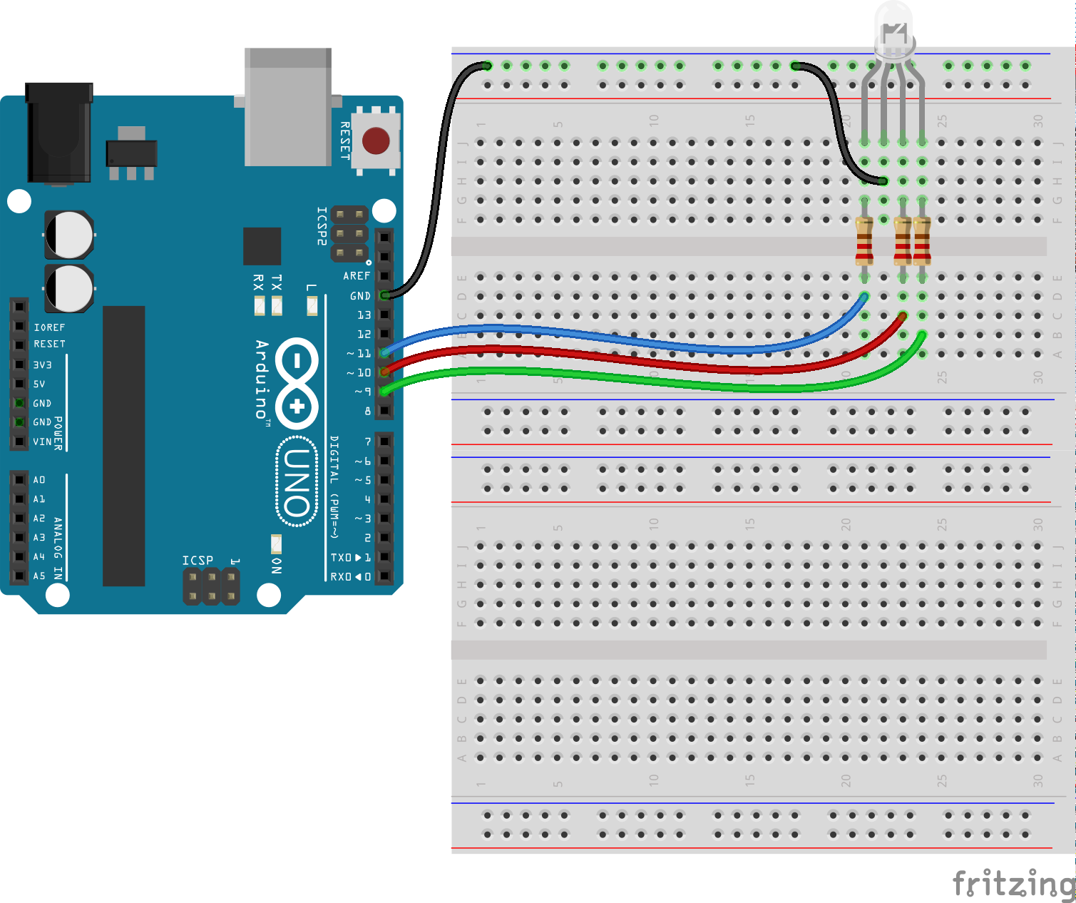
Code
int redPin = 11; int greenPin = 10; int bluePin = 9; //uncomment this line if using a Common Anode LED //#define COMMON_ANODE void setup() { pinMode(redPin, OUTPUT); pinMode(greenPin, OUTPUT); pinMode(bluePin, OUTPUT); } void loop() { setColor(255, 0, 0); // red delay(1000); setColor(0, 255, 0); // green delay(1000); setColor(0, 0, 255); // blue delay(1000); setColor(255, 255, 0); // yellow delay(1000); setColor(80, 0, 80); // purple delay(1000); setColor(0, 255, 255); // aqua delay(1000); } void setColor(int red, int green, int blue) { #ifdef COMMON_ANODE red = 255 - red; green = 255 - green; blue = 255 - blue; #endif analogWrite(redPin, red); analogWrite(greenPin, green); analogWrite(bluePin, blue); } -
Control LED Brightness (Analog Input/Output & Serial)
Components: 1x LED, 1x Potentiometer, 1x Resistor (220 Ohms)
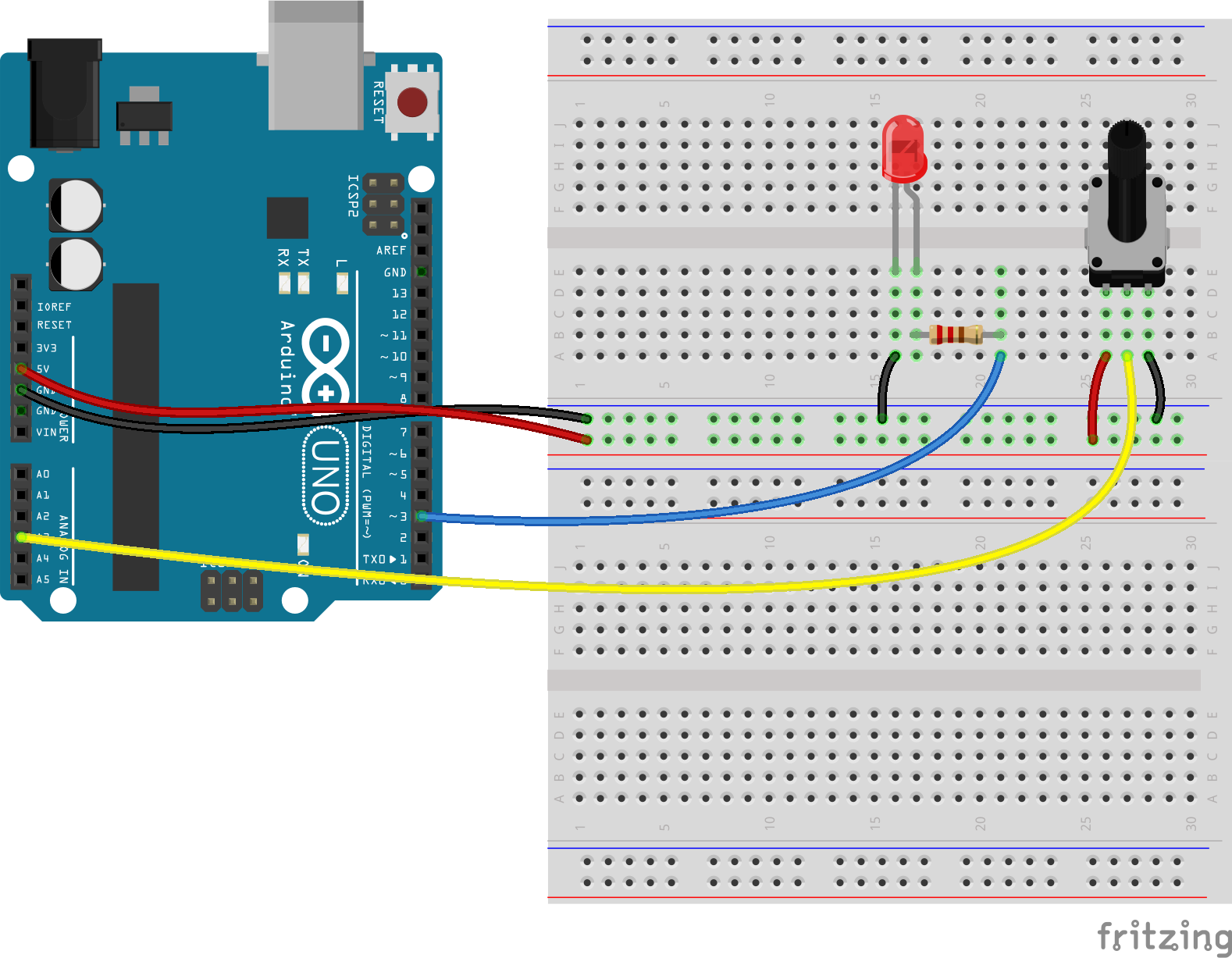
Code
 // These constants won't change.  They're used to give names
 // to the pins used:
 const int analogInPin = A2;  // Analog input pin that the potentiometer is attached to
 const int analogOutPin = 3; // Analog output pin that the LED is attached to

 int sensorValue = 0;        // value read from the pot
 int outputValue = 0;        // value output to the PWM (analog out)

 void setup() {
   // initialize serial communications at 9600 bps:
   Serial.begin(9600);
 }

 void loop() {
   // read the analog in value:
   sensorValue = analogRead(analogInPin);
   // map it to the range of the analog out:
   outputValue = map(sensorValue, 0, 1023, 0, 255);
   // change the analog out value:
   analogWrite(analogOutPin, outputValue);

   // print the results to the serial monitor:
   Serial.print("sensor = ");
   Serial.print(sensorValue);
   Serial.print("\t output = ");
   Serial.println(outputValue);

   // wait 2 milliseconds before the next loop
   // for the analog-to-digital converter to settle
   // after the last reading:
   delay(2);
 }